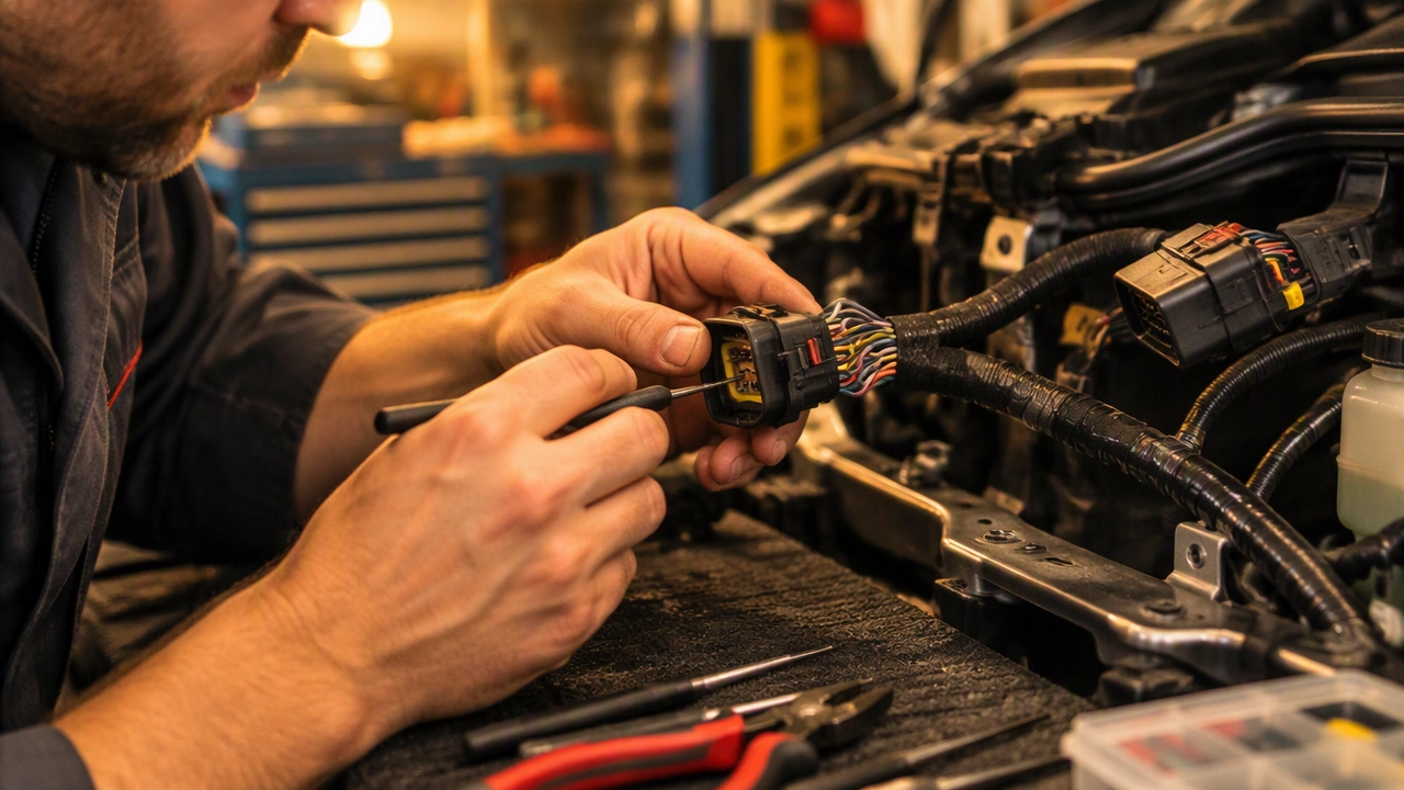
Home / Electrical & Electronics
Car Repair in the Workshop: Automotive Wiring Harness and Connector Repair Techniques
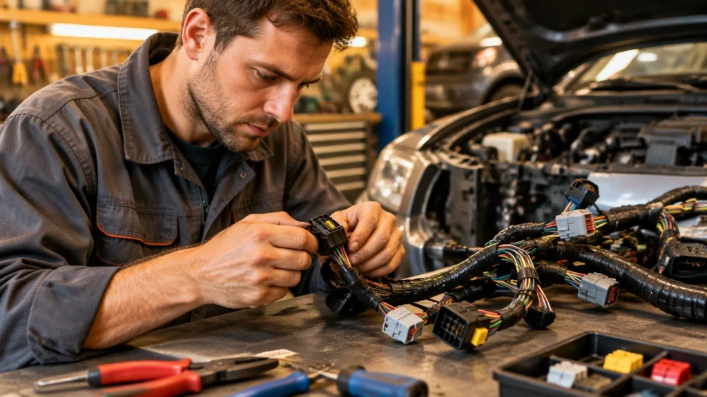
Modern vehicles depend on clean, reliable electrical paths for engine management, safety systems, comfort features, and charging. When a harness is damaged or a connector fails, technicians follow a structured process to restore circuit integrity without creating new fault points. This article explains how a workshop approaches automotive wiring harness and connector repair techniques, from initial diagnosis to final verification and protection.
Understanding the wiring harness and connector layout
A wiring harness is a bundled set of conductors that routes power and signals throughout the vehicle. It includes wires of different gauges, shielded cables for sensitive circuits, splices, terminals, and multi-pin connectors. Each connector is designed to lock securely, resist moisture, and maintain low contact resistance. In workshops, accurate repair starts with understanding how these assemblies are routed, supported, and sealed.
Technicians review connector keying, terminal type, and cavity positions. They also check for service loops, strain reliefs, and protective coverings such as tape, conduit, or braided sleeving. This context matters because a repair that restores continuity but ignores routing or protection often fails under vibration, heat, or water exposure.
Common causes of harness and connector damage
- Mechanical abrasion from rubbing against brackets, engines, or body panels
- Heat exposure near exhaust components or turbo systems
- Moisture intrusion into poorly sealed connectors
- Corrosion caused by battery acid, road salt, or condensation
- rodent damage or improper previous repairs
- Stress fractures at tight bends or at connector entries
Workshop diagnosis focuses on reproducing the customer complaint while inspecting these common failure points. A systematic approach prevents misdiagnosis and unnecessary part replacement.
Diagnostic process in the workshop
Gathering information and visual inspection
Technicians begin with a detailed interview about symptoms, driving conditions, and when the fault occurs. A visual inspection follows: they look for chafed insulation, backed-out terminals, melted plastic, water stains, green corrosion on pins, and broken locks. They also check for recent service work that may have disturbed connectors.
Electrical testing
Using a digital multimeter, technicians measure voltage drops, resistance, and continuity. For intermittent faults, they perform a wiggle test while monitoring live data or circuit behavior. They may back-probe connectors without damaging seals and use low-current test leads on sensitive circuits. Smoke testing can reveal hidden harness breaches in sealed systems, and oscilloscope checks help confirm signal integrity on communication networks.
The goal is to isolate the exact pin, splice, or wire segment that is failing, and to understand whether the issue is mechanical, thermal, or chemical.
Planning the repair
Once the fault is confirmed, the technician selects a repair strategy that preserves original performance. Planning includes:
- Choosing the correct wire gauge and insulation type for the circuit
- Selecting terminals that match the connector family and cavity size
- Deciding whether to repair a single conductor or replace a section of the harness
- Ensuring access for future service without compromising protection
Good planning avoids shortcuts and ensures the repair fits the vehicle’s environment.
Automotive wiring harness and connector repair techniques
Wire preparation
Technicians remove damaged insulation carefully, avoiding nicks to the conductor. They clean corrosion with approved contact cleaners and a small fiberglass brush when needed. The wire is cut back to clean copper, and the length of the strip matches the terminal or splice specification. Proper preparation ensures strong mechanical contact and a reliable solder joint.
Connector and terminal service
When a terminal is damaged, the technician depins the connector using the correct release tool. They inspect the cavity for melting or spread locks. If the housing is compromised, they replace it with an OEM or equivalent part. New terminals are crimped using calibrated tools that create a gas-tight barrel connection. A good crimp shows a visible indentation, no frayed strands, and secure insulation support.
For sealed connectors, they replace rubber seals and ensure each cavity retains its seal ring. They also verify that the connector lock clicks fully during reassembly.
Soldering and insulation
Soldering is used where the repair benefits from a bonded joint, such as a mid-span splice. Technicians tin the wire ends, align the conductors, and flow solder to create a smooth, bright joint without excess blob. They avoid cold joints, overheating, and wicking that can stiffen the wire. After soldering, they insulate with adhesive-lined heat-shrink tubing that seals against moisture. Where appropriate, they use solder-seal connectors that combine solder and insulation in one step, following the manufacturer’s guidance.
In areas exposed to high heat or fluids, they select high-temperature insulation materials. In standard areas, they choose insulation that balances flexibility and durability.
Mechanical splices and crimps
In some cases, a quality crimp splice is preferred over solder, especially where flexibility and vibration resistance are critical. Technicians use calibrated crimp tools and OEM-type butt connectors with insulation that matches the circuit environment. They check pull strength gently and confirm the splice does not create a stiff point in the harness.
Protection and routing
After the electrical connection is restored, protection is critical. Technicians wrap repaired areas with OEM-spec tape, install conduit or braided sleeving, and restore grommets at panel pass-throughs. They re-secure clips and tie-downs to maintain factory routing. Strain reliefs are added near connectors to reduce movement at the terminal entry. This step prevents repeat failures from abrasion, heat, or vibration.
Testing and quality checks
Workshops verify the repair with a repeat of the original diagnostic tests. They confirm voltage drop is within specification, resistance is stable, and the circuit behaves normally under load. For networked systems, they check for communication errors and clear any stored fault codes after a drive cycle. They also inspect the physical repair for correct insulation, secure locks, and proper routing. Documentation includes photos, test results, and parts used.
When replacement is the better option
Some situations call for harness section replacement rather than repair. Severe heat damage, extensive corrosion, multiple faults in one branch, or compromised shielding may make a targeted repair unreliable. In these cases, technicians install a new harness section, follow the factory routing, and ensure all seals and fasteners are correctly restored.
Preventive advice for vehicle owners
- Address check engine or electrical warnings early to reduce secondary damage
- Keep battery terminals clean and secure to lower stress on charging circuits
- Avoid aftermarket accessories that tap into factory wiring without proper fusing and routing
- Ask the workshop to inspect harness protection during major services
With careful diagnosis, proper materials, and disciplined technique, workshops restore reliable electrical performance. These automotive wiring harness and connector repair techniques help ensure that repaired circuits last, even in demanding driving conditions.